All projects

Lightbox

Designed and built a custom PCB, wrote state-machine C++ firmware on an Arduino Nano Every, and 3D-printed a fitted enclosure to create a button and potentiometer-controlled LED device.
Role
Medical Device Design Skills | Duke University
Timeframe
Spring 2025

Problem / Goal

The goal was to build a functional LED lightbox from the ground up as a full-stack embedded systems exercise in a medical device design course at Duke. The device had to respond to button and potentiometer inputs, with control logic managed by state-machine firmware running within the memory constraints of an Arduino.

What I Did

I started by building state diagrams to map the control logic before writing any firmware, then implemented it in C++ on an Arduino Nano Every using PlatformIO, with hardware interrupts driving state transitions. I managed all project files in a Git repository throughout.
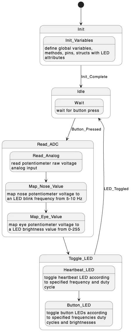
State machine diagram with Init, Idle, Read_ADC, and Toggle_LED states connected by labeled transitions
Firmware state machine — button press triggers ADC read and LED toggle, returning to idle on completion

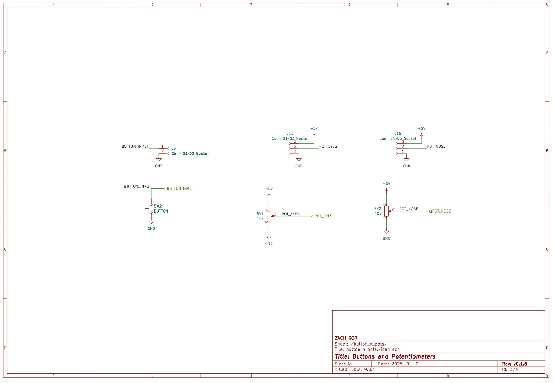
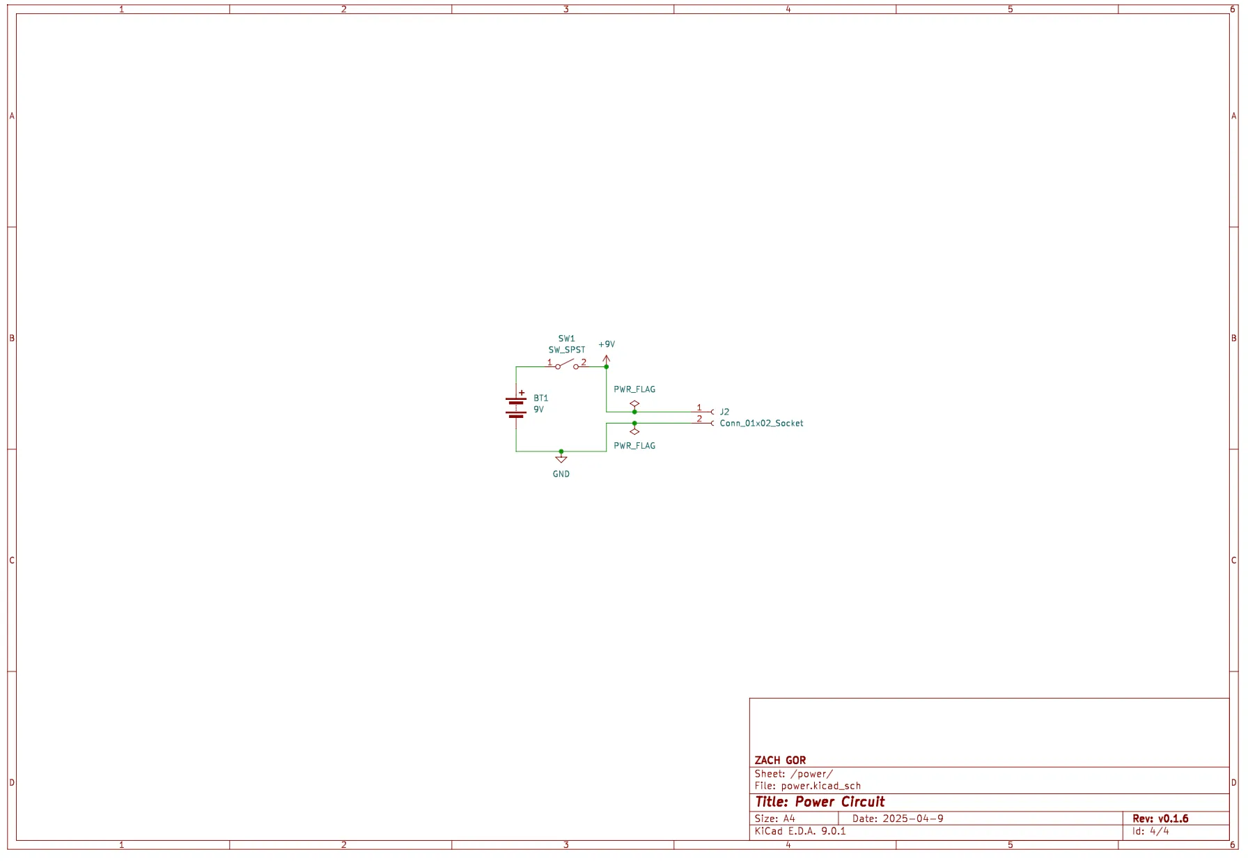
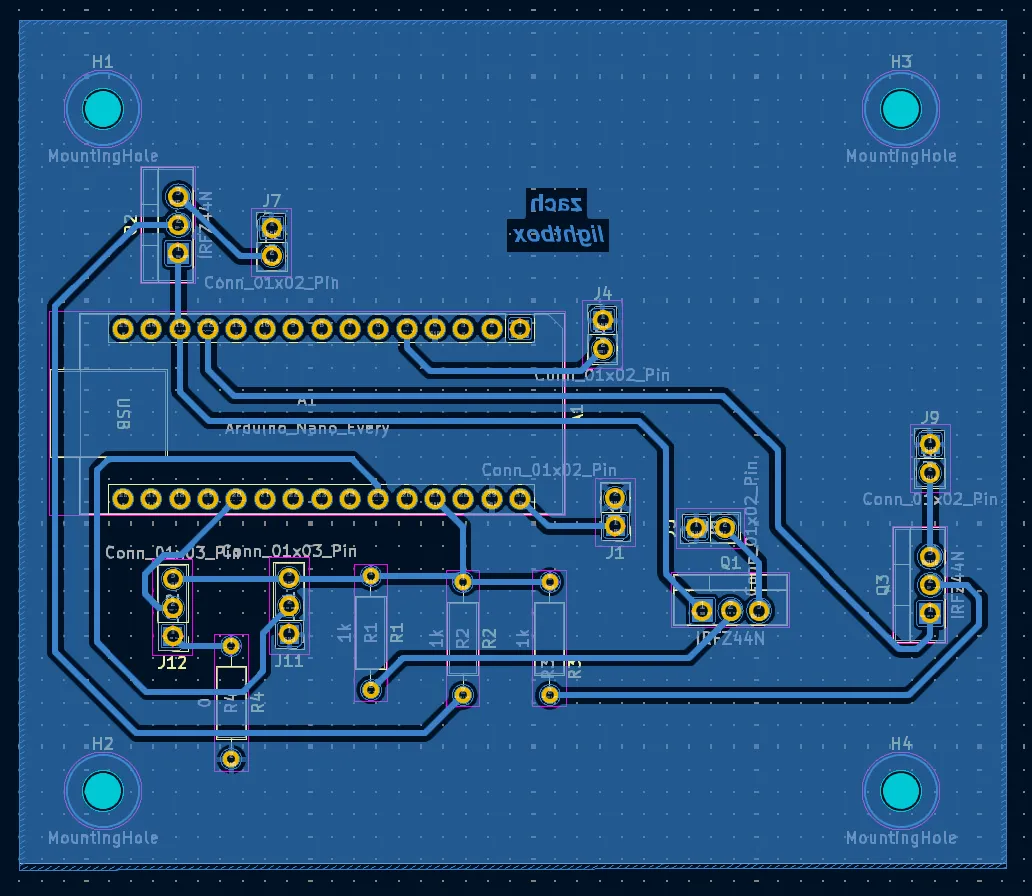
On the electrical side, I designed the schematic and PCB layout in KiCad, ran ERC and DRC checks, and ran SPICE simulations to verify circuit behavior before cutting the board. After fabrication, I soldered the components and confirmed connectivity at each stage with a multimeter.
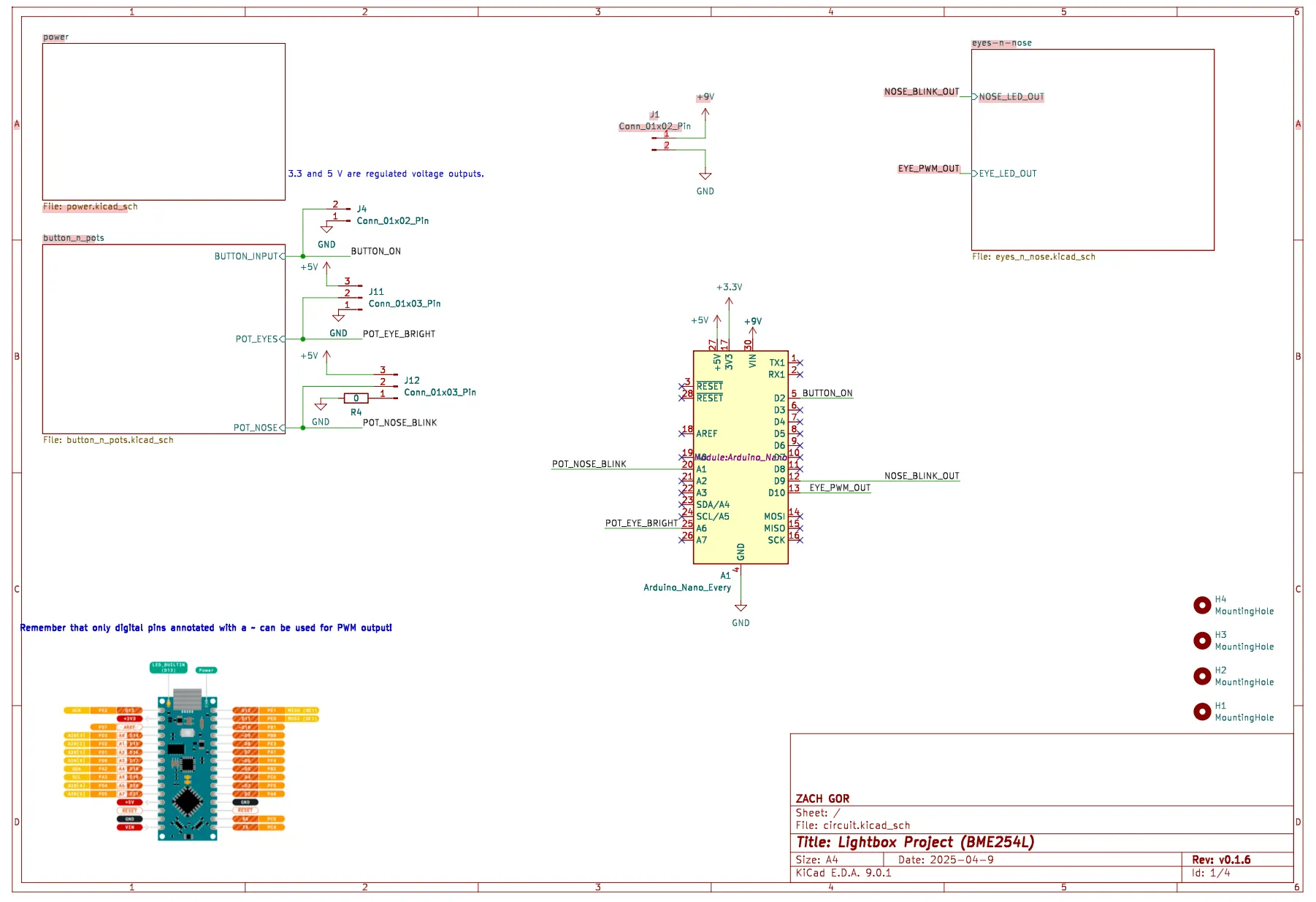
Top-level KiCad schematic showing the Arduino Nano Every connected to power, button/potentiometer inputs, and LED output subsystems
Top-level schematic (sheet 1/4): Arduino Nano Every with labeled signal connections to each subsystem
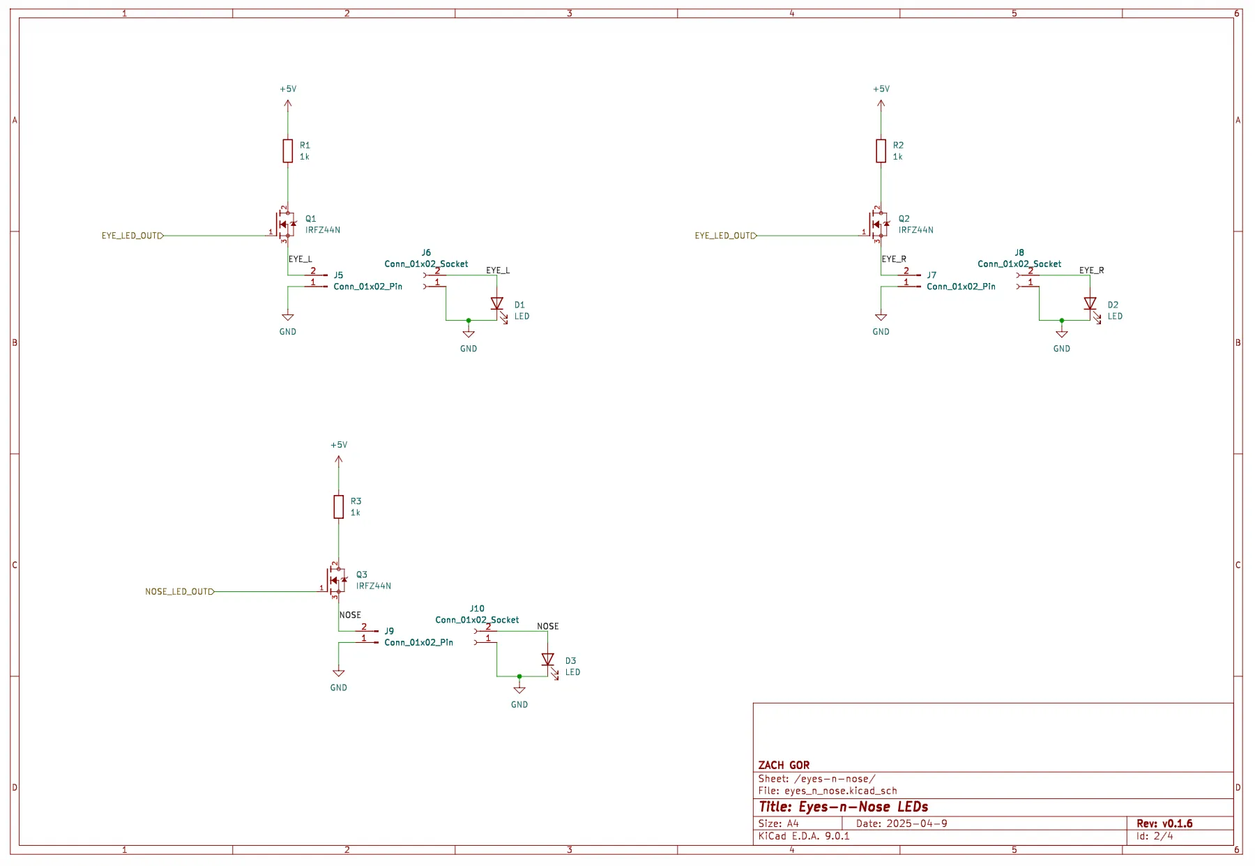
Schematic showing three MOSFET-driven LED circuits for left eye, right eye, and nose outputs
Eyes-n-nose LED sub-sheet (2/4): IRFZ44N MOSFETs switching each LED output independently
Schematic showing a momentary button switch and two 10k potentiometer inputs
Button and potentiometer input sub-sheet (3/4)
Power circuit schematic with a 9V battery, SPST power switch, and output connector
Power sub-sheet (4/4): 9V battery with SPST switch feeding the board
KiCad PCB layout showing component footprints, copper traces, and four mounting holes
PCB layout with components placed and traces routed
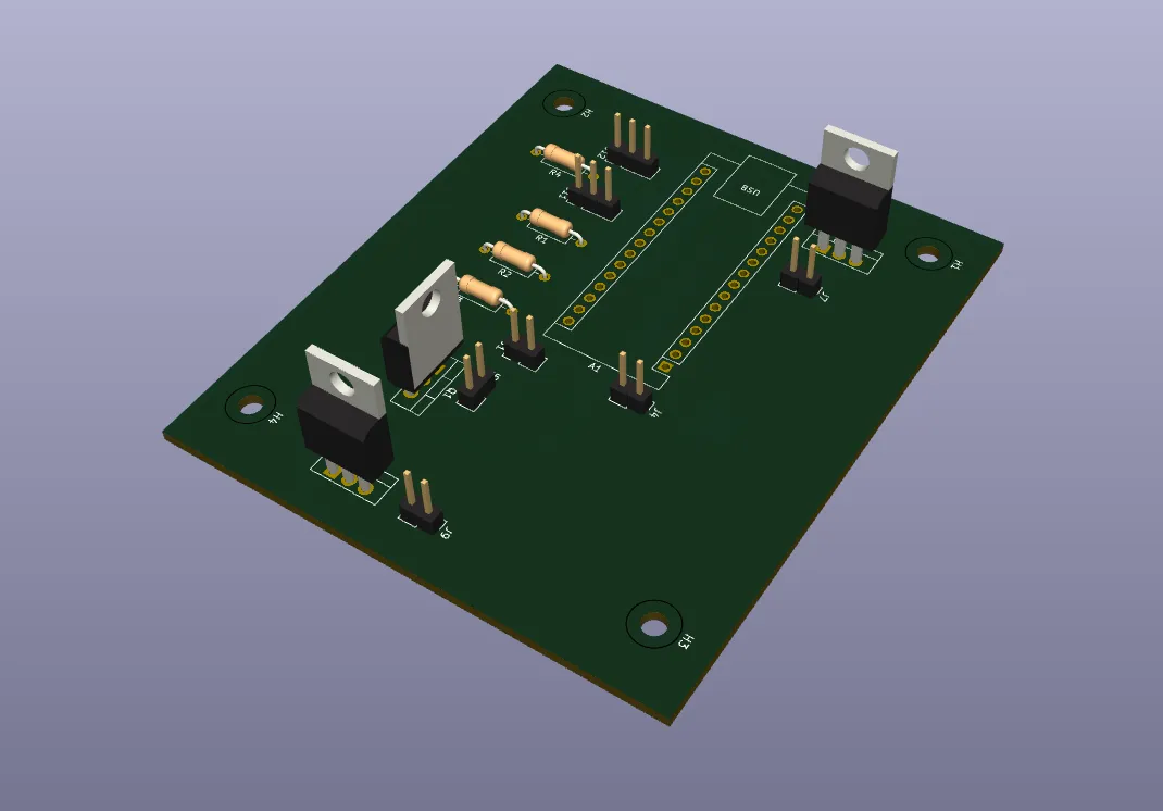
KiCad 3D render of the PCB front side showing MOSFETs, resistors, and header connectors
Front-side 3D render prior to fabrication
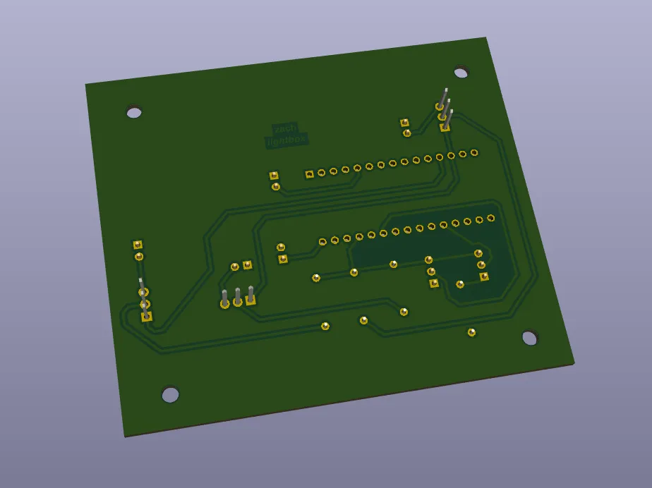
KiCad 3D render of the PCB back side showing copper trace routing and silkscreen label
Back-side 3D render showing trace routing

For the enclosure, I modeled it in Onshape to fit the PCB exactly, 3D printed it, and assembled everything with heat-set inserts.
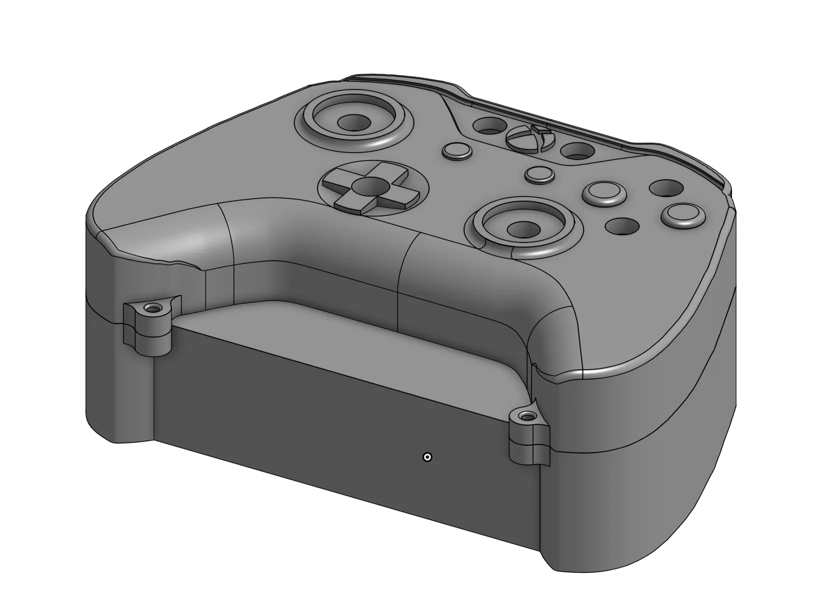
Onshape CAD model of the Xbox controller-shaped two-part enclosure showing the top shell and base
Enclosure model in Onshape — Xbox controller form factor chosen to fit all components and controls at natural positions

Results

A fully functional device: working PCB, fitted enclosure, and firmware handling all input and LED control logic as designed.
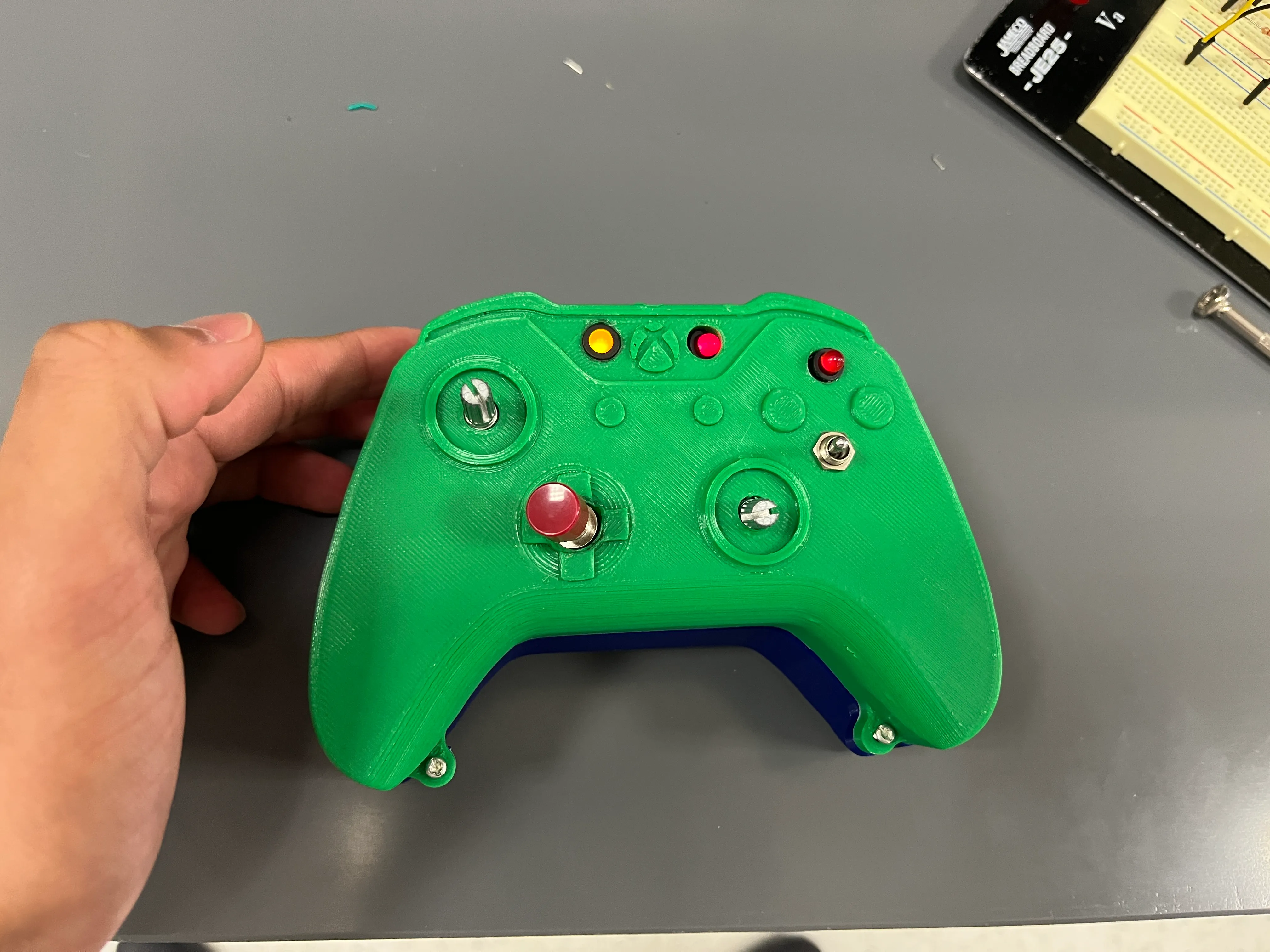
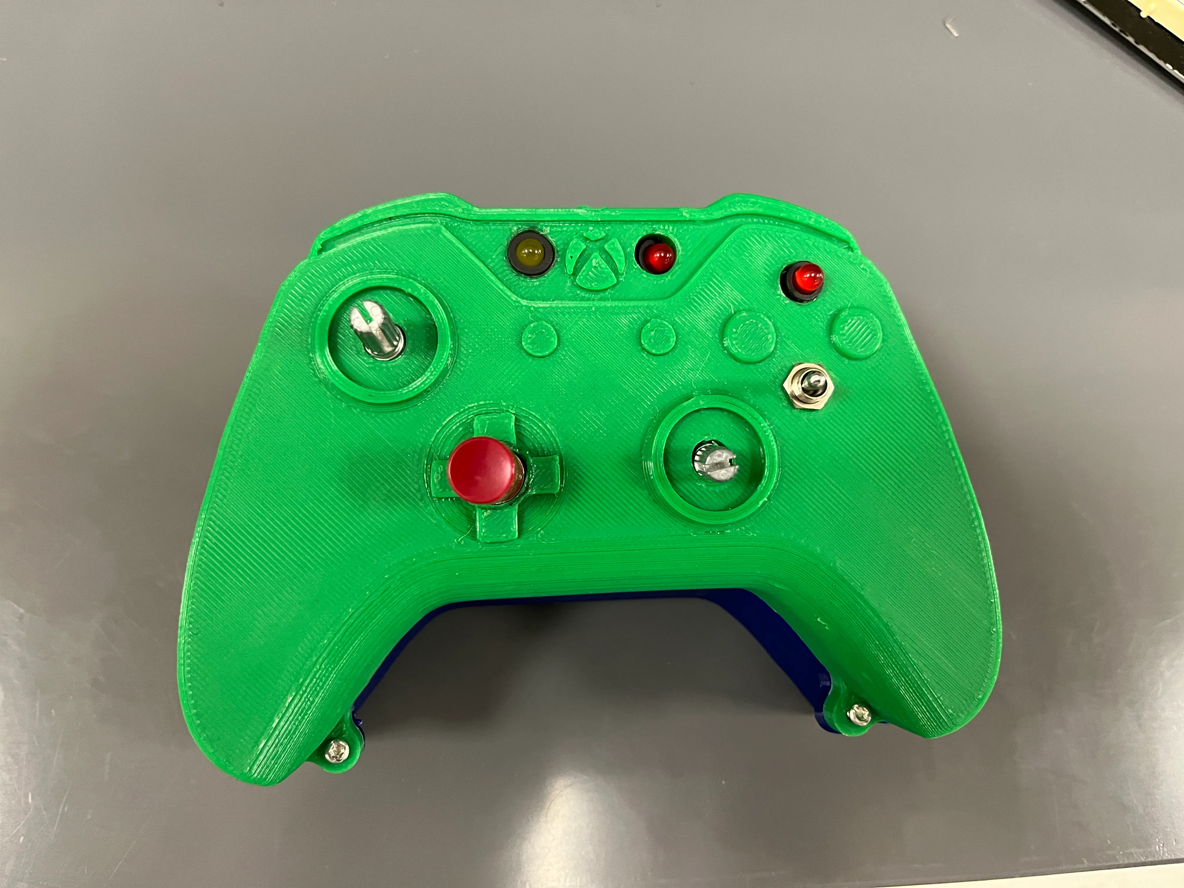
Completed lightbox device from the front — green 3D-printed controller enclosure with potentiometers, toggle switches, and three LEDs
Completed device with all controls and LEDs mounted in the printed enclosure
Hand holding the assembled device at an angle, with the yellow and red LEDs lit
LEDs active during a test run
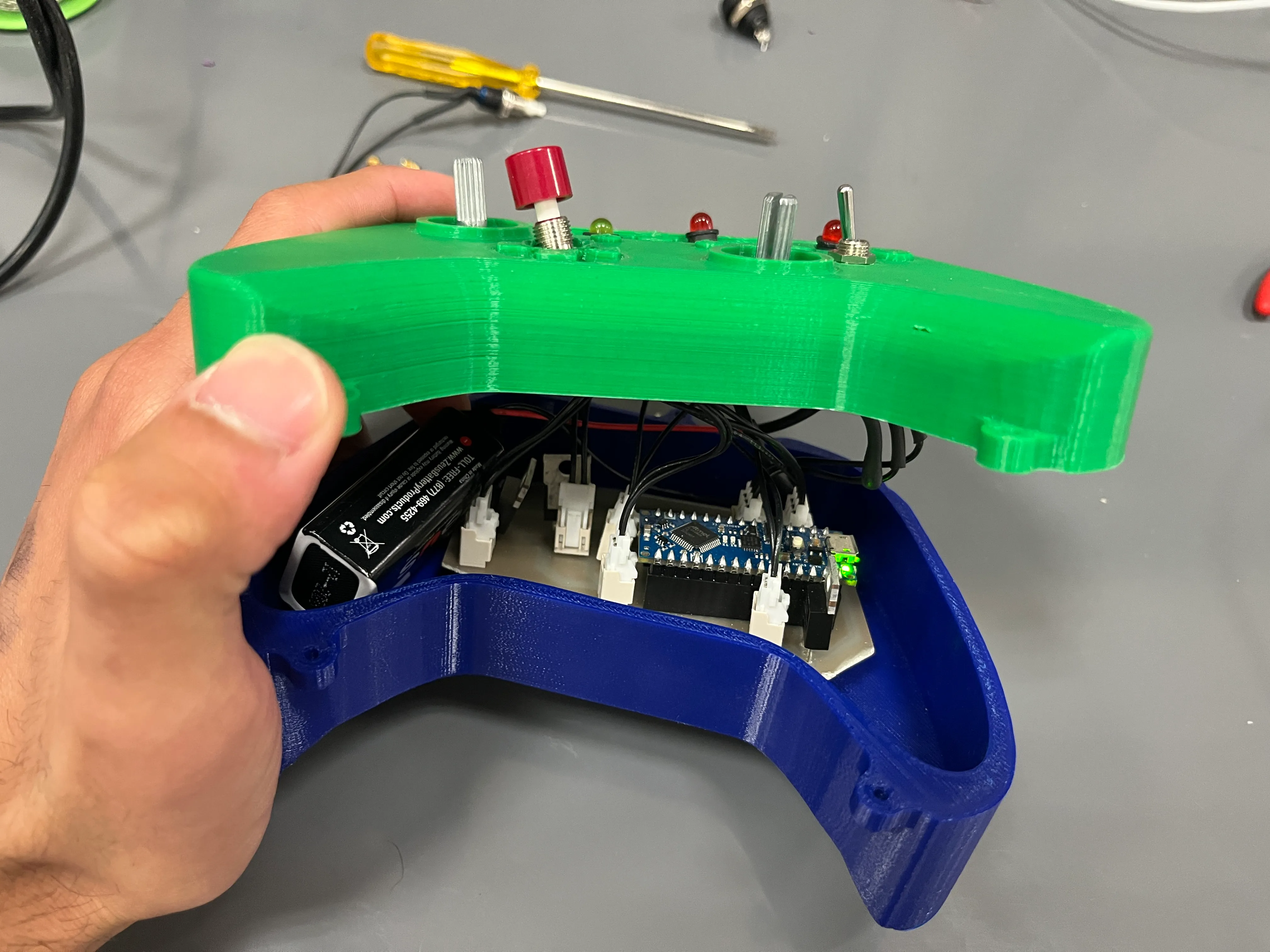
Device with top shell lifted open, showing the PCB, Arduino Nano Every, wiring, and 9V battery seated inside
Interior with the top shell raised, showing how the PCB and battery pack fit in the enclosure
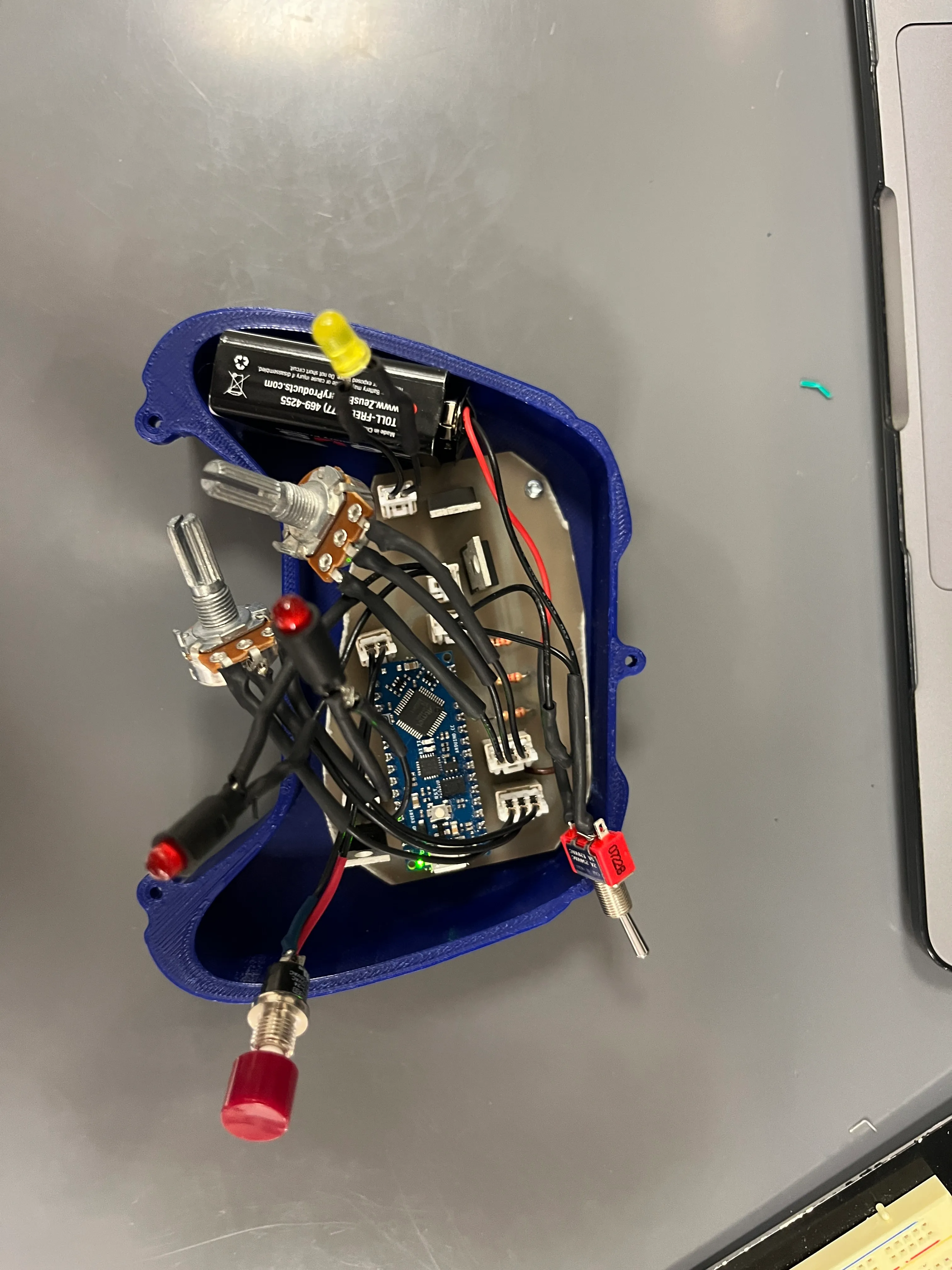
Top-down view of the open base half, showing the PCB, connectors, potentiometers, and wiring laid out inside the blue shell
Base half open, showing the full internal assembly

What I Learned

This was the first time I built every layer of an electromechanical system myself. Working through schematic, firmware, and enclosure in sequence made the dependencies between them concrete in a way that isolated exercises don’t capture. A layout choice affects solderability; a firmware architecture shapes memory usage; an enclosure dimension constrains everything that goes inside it.