VVI Pacemaker Circuit
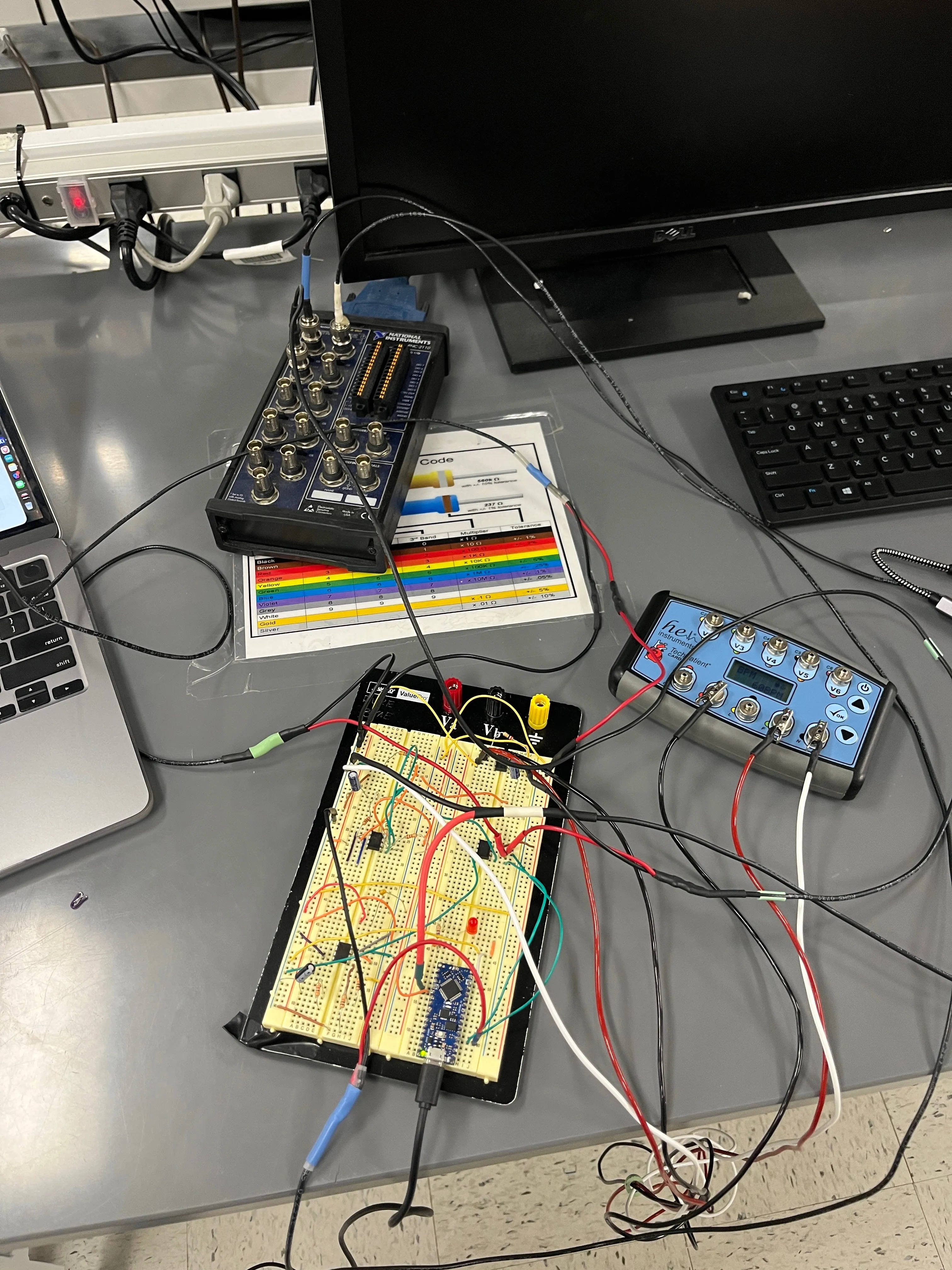
Designed and built an analog circuit that filters and amplifies a noisy ECG signal, detects cardiac pulses, and delivers stimuli to maintain a target heart rate.
Problem / Goal
Bradycardia — an abnormally slow heart rate — is one of the most common indications for pacemaker implantation, affecting a significant share of adults over 65. A VVI pacemaker addresses it by monitoring the heart’s electrical activity and delivering a stimulus whenever the native rate drops below a set threshold, pacing only as needed.
For a bioinstrumentation course at Duke, the assignment was to build one from scratch: a circuit that reads raw ECG data from a signal generator, extracts cardiac pulses from that noisy signal, detects when the rate falls below target, and delivers the appropriate pacing output.
What I Did
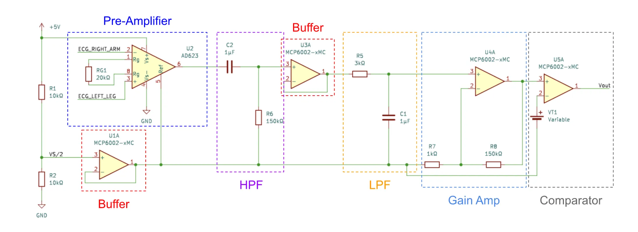
The ECG signal coming off the electrodes is weak and buried in noise, so the circuit had to condition it through several stages before anything useful could be done with it.
The first stage was a pre-amplifier built around an AD623 instrumentation amplifier. The gain was tuned to bring the signal up to a workable voltage range without clipping. From there, the signal went through a bandpass filter. Resistor and capacitor values were chosen to pass the 8–30 Hz range where the R wave lives and reject everything outside it, including low-frequency baseline drift and high-frequency interference.
A second amplification stage using an MCP6002 op-amp in a non-inverting configuration brought the filtered signal up further, with resistor values set to hit the target gain. The conditioned signal then fed into the Arduino’s ADC, sampled at a rate comfortably above Nyquist to capture the waveform faithfully.
The pacing logic ran in firmware. The code used hardware interrupts to detect R-wave peaks in the digitized signal, tracked the interval between beats, and triggered a stimulation output whenever that interval exceeded the escape threshold. Throughout the build, I validated each stage before moving to the next. I measured empirical time constants and transfer functions to confirm filter performance, and used a DMM and oscilloscope to verify the signal at each point in the chain.
Results
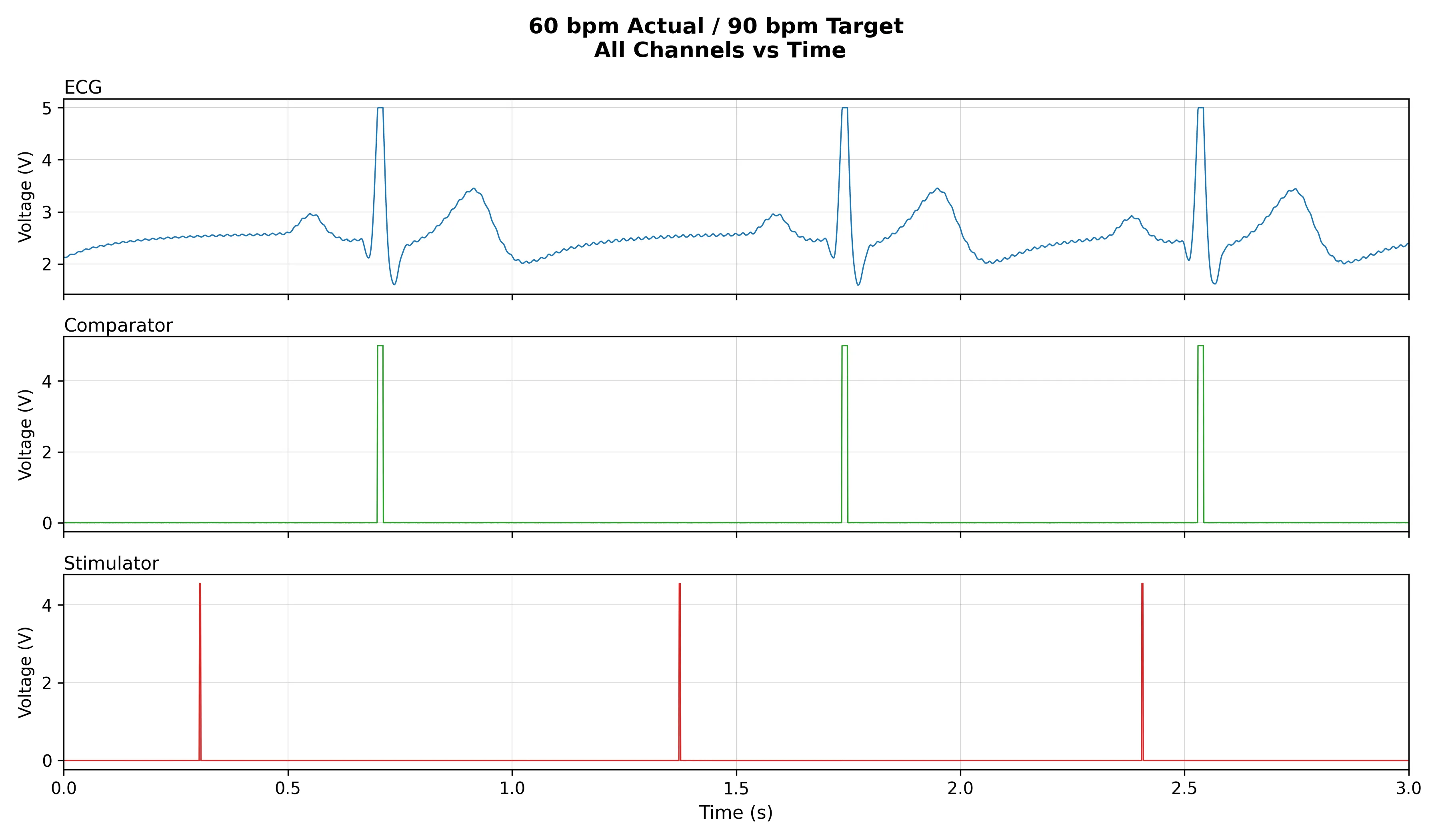
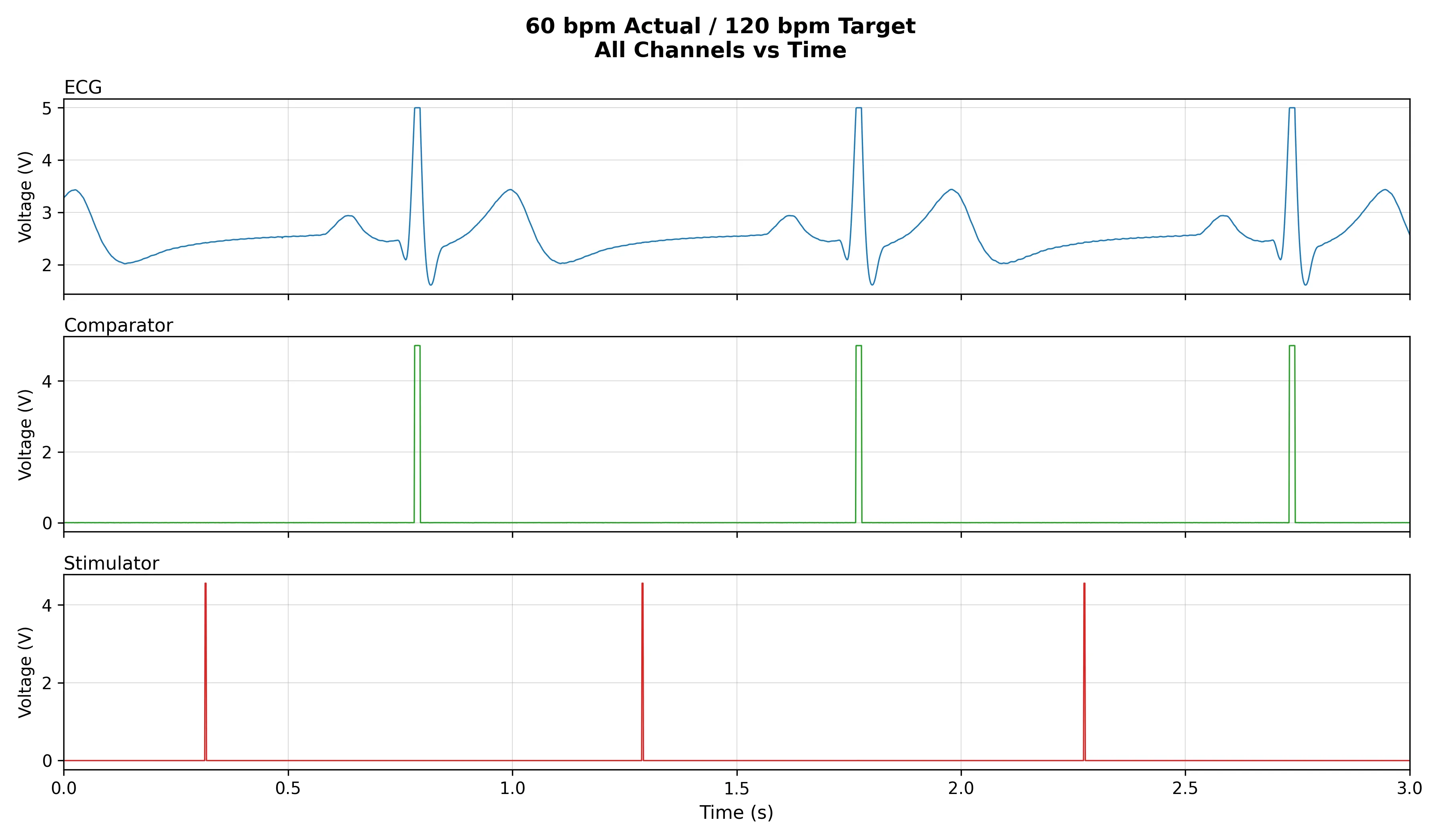
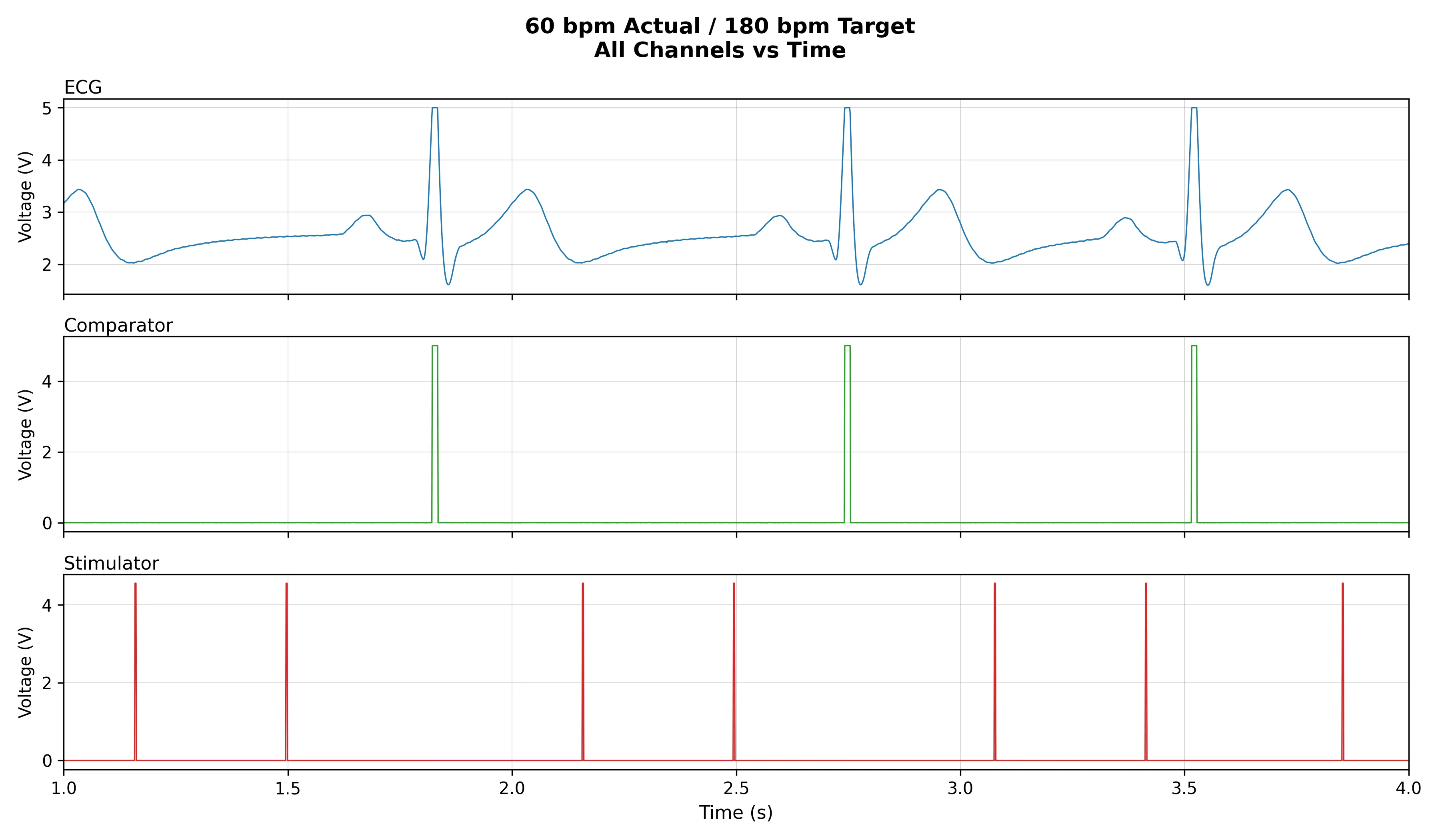
The circuit worked end-to-end: filtered and amplified ECG input, reliable R-wave detection, and pacing output triggered correctly when the simulated heart rate dropped below threshold.
What I Learned
Most of my prior circuit work had been digital. This project pushed me into analog territory — op-amp gain stages, RC filter design, transfer functions — areas I had studied but never built from scratch. Working through the full signal chain, validating each stage on the bench, and chasing down noise and drift gave me a much more concrete feel for analog design than coursework alone had. I came out of it significantly more comfortable reading and debugging live circuits, and with a clearer instinct for how biosignals need to be conditioned before they can be acted on.